Symmetrical Components
Electrical systems are engineered and constructed to ensure optimal performance and dependable operation whenever needed. This is fundamental to all power systems. But this may not always be the case. What are sequence or symmetrical components?
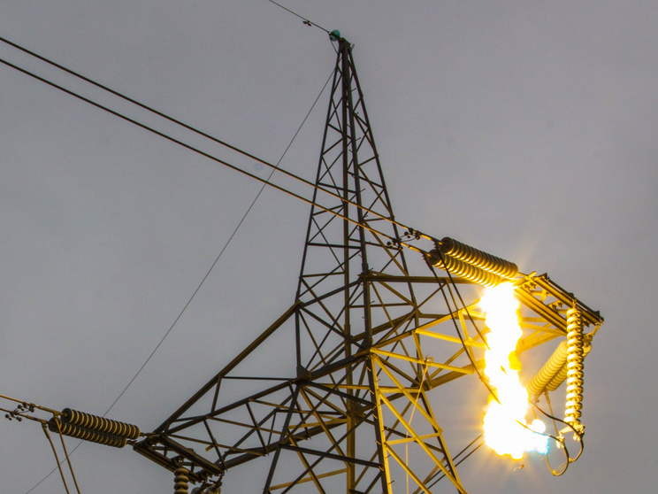
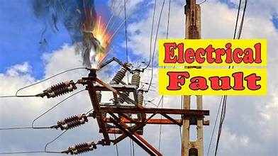
However, disturbances create undesirable conditions that lead to faults. Disturbances in power systems often arise from factors such as human errors (e.g., design flaws, operational missteps, or mismatched applications), intentional human actions like cyberattacks, and natural phenomena including thunderstorms, floods, and similar events.
Following a fault, it must be resolved promptly and at the most suitable moment to avoid unnecessary delays. However, a significant delay without purpose only worsens the devastation such as burning of facilities or properties, injury or death.
Nonetheless, to enhance fault analysis, event records are extracted from protective devices (relays). These records are then analyzed to determine the root cause of the fault(s), the time of occurrence, and whether the fault(s) were properly cleared.
Engineers or technicians take mitigation action to address the disturbance(s) based on the understanding of the system and the nature of the fault.
In this post, we will briefly discuss one of the most important and popular way to troubleshoot electrical faults. That is, the use of sequence components is important to understand faults.
The concept of symmetrical components was first presented in Atlantic City, New Jersey by Charles LeGeyt Fortescue at the 34th Annual Convention of the American Institute of Electrical Engineers [1]. Fortescue’s paper was “Method of Symmetrical Coordinates Applied to the Solution of Polyphase Networks”. For the past 100 years, symmetrical components has been beneficial in fault analysis of three-phase electrical systems.
Table of Contents
Illustration of Original Phasors and Sequence Components
Live Data Captured from a Relay's Human Machine Interface (HMI)
The HMI’s displayed phase values clearly indicate an imbalance among the phase currents: IA, IB, and IC. As such, this resulted in a ground fault current calculated by the relay as IG.
What is the importance of the calculated IG?
Using the captured data at the end of the video to calculate the sequence or symmetrical components (I1, I2, and I0).
Where:
I1 = Positive sequence current:
I2 = Negative sequence current:
I0 = Zero sequence current:
Given phase currents and ground fault (IG);
IA = 8.10A < 166.20 °
IB = 4.70A < 37.30°
IC = 7.50A < -99.50°
IG = 5.90A < 154.50°
Note: Voltages look nearly balanced and will not be considered in our analysis here. However, the same understanding applies to both currents and voltages in analyzing symmetrical components [2].
For clarity, we performed hand calculations and attached the solutions in Figures 1 to 4. In reality, protection relays handle these kinds of computations to perform protection functions. However, the understanding of this application is important for analyzing faults and performing protection settings.
Symmetrical Components Calculation of Unbalanced Three-Phase System
Figure 1 reveals that the phase currents: IA, IB, and IC—are unbalanced in both magnitude and angular displacement (+/-120°). Using phase A as reference, the angle of separation between IA and IB is 166.20° – 37.3° = 128.9° and from IB and IC is 37.3° – (-99.5°) = 136.8°.

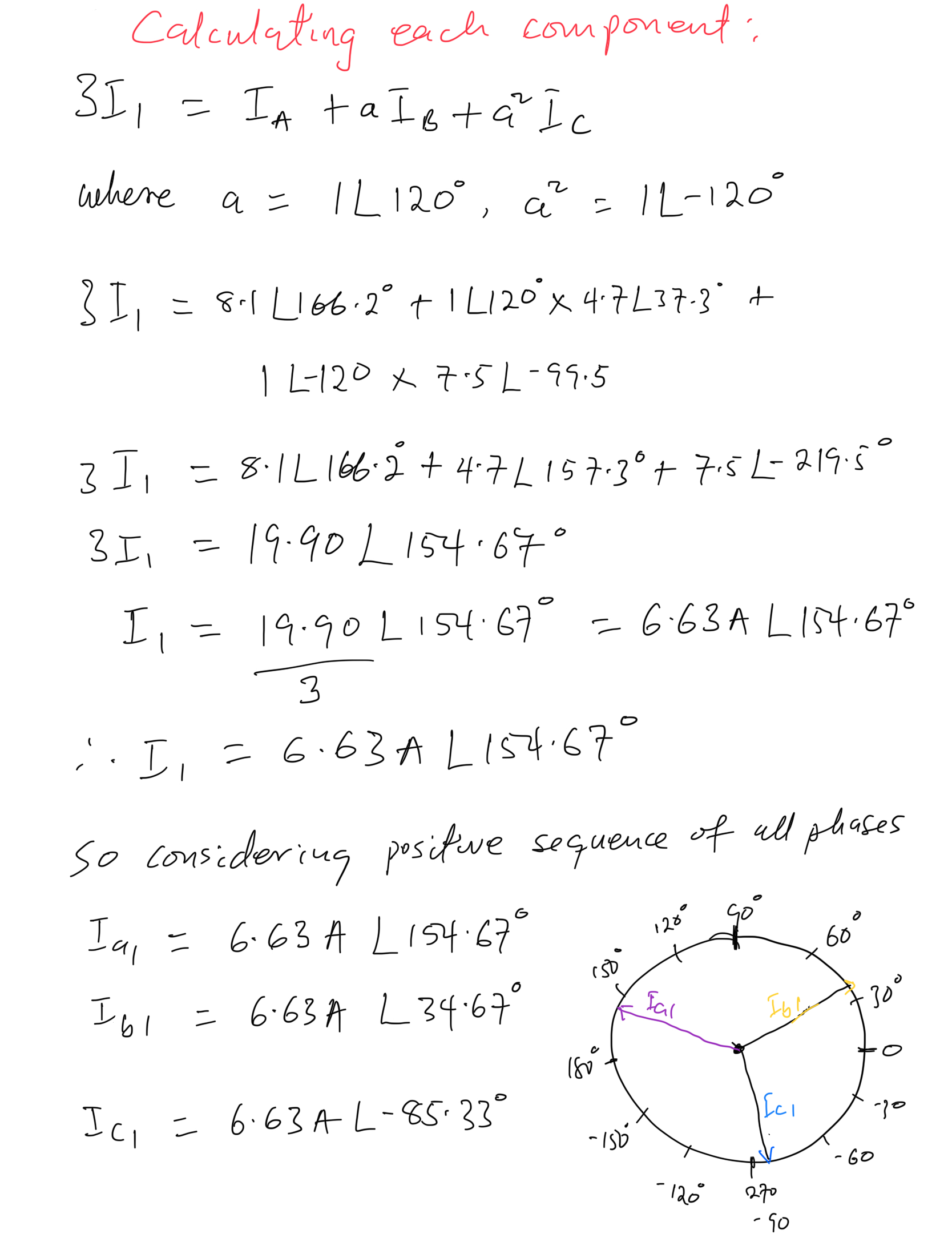
Positive Sequence Current Calculation
Positive Sequence Current (I1): three current phasors with equal magnitudes displaced at +/-120°. (ABC phase rotation in counterclockwise display as shown in Figure 2).
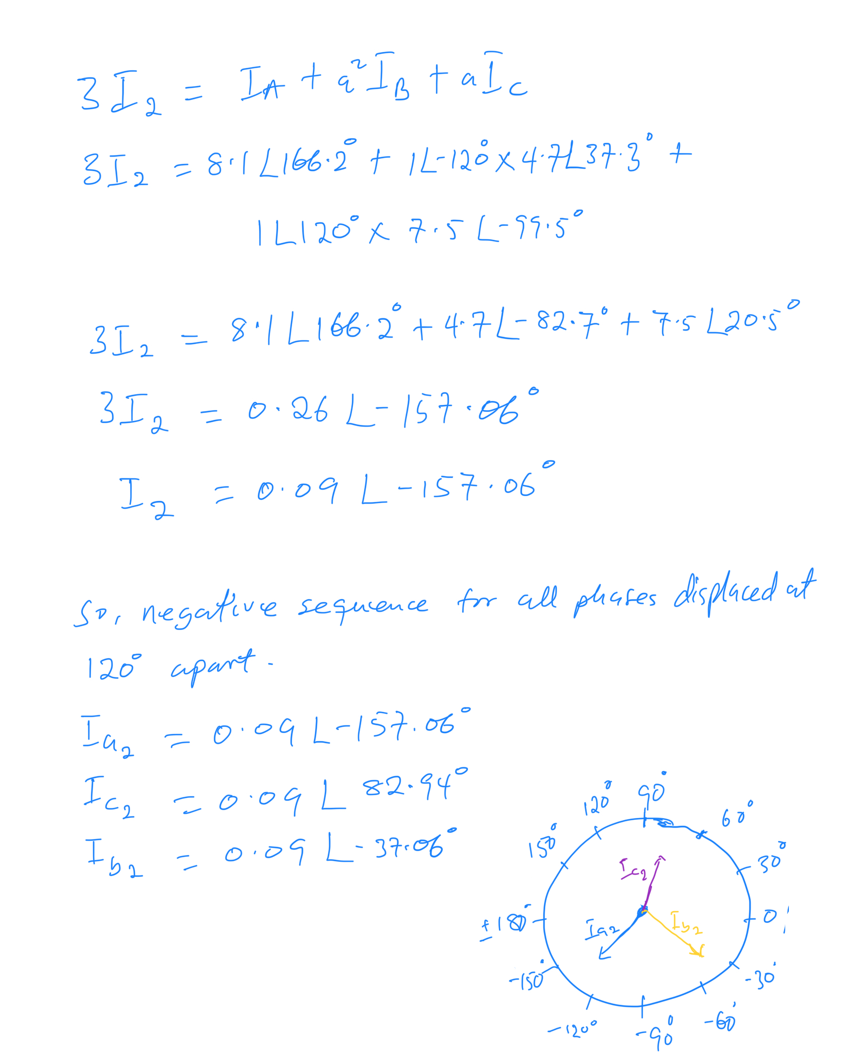
Negative Sequence Current Calculation
Negative Sequence Current (I2): three current phasors with equal magnitudes displaced at +/-120°. (ACB phase rotation in counterclockwise display as shown in Figure 3).
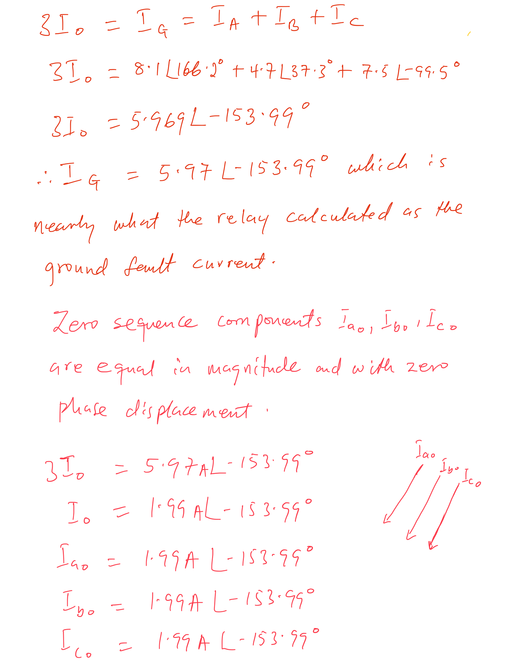
Zero Sequence Current Calculation
Zero Sequence Current (I0): consist of three current phasors with equal magnitudes and no phase displacement as shown in Figure 4. That is the angle of separation between the phasors is zero.
Symmetrical Components Calculation of Balanced Three-Phase System
Figure 5 shows another example of data I captured from a relay after commissioning it.
In this example, the magnitudes of the phase currents are nearly equal. That is IA = 108.0333A, IB = 108.817A, and IC = 107.968A. However, the phase displacement angles are not +/-120° apart.
IA – IB = 139.05° – 79.52° = 59.53°
IB – IC = 79.52° – 19.14° = 60.38°
IC – IA = 19.14° – 139.05 = -119.91°
IA and IC maintain nearly a 120° displacement; however, the system remains unbalanced due to the influence of the other two phasors.
This gives an indication that there relay will calculate a ground fault current (IG) and compare it to the pickup setting.
First Scenario: System is Unbalance Based on Displaced Angles
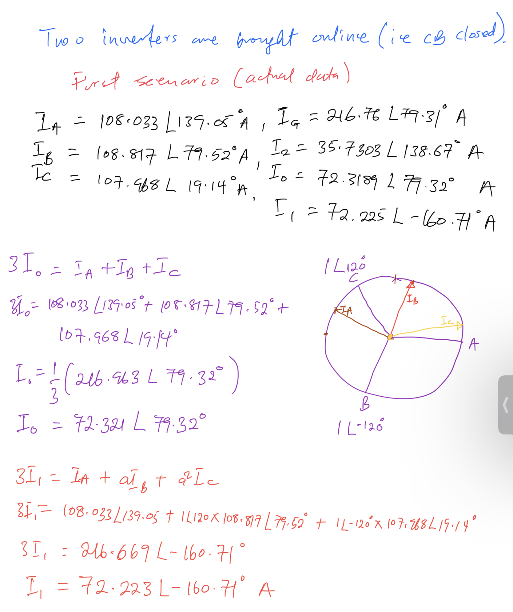
Both zero and positive sequence currents are similar in magnitude as shown in Figure 5 above. Is this a problem?
Second Scenario: System is Balance Based on Displaced Angles
However, in this second scenario, we keep the magnitudes constant and adjust the displaced angles to achieve balance (based on the assumption).
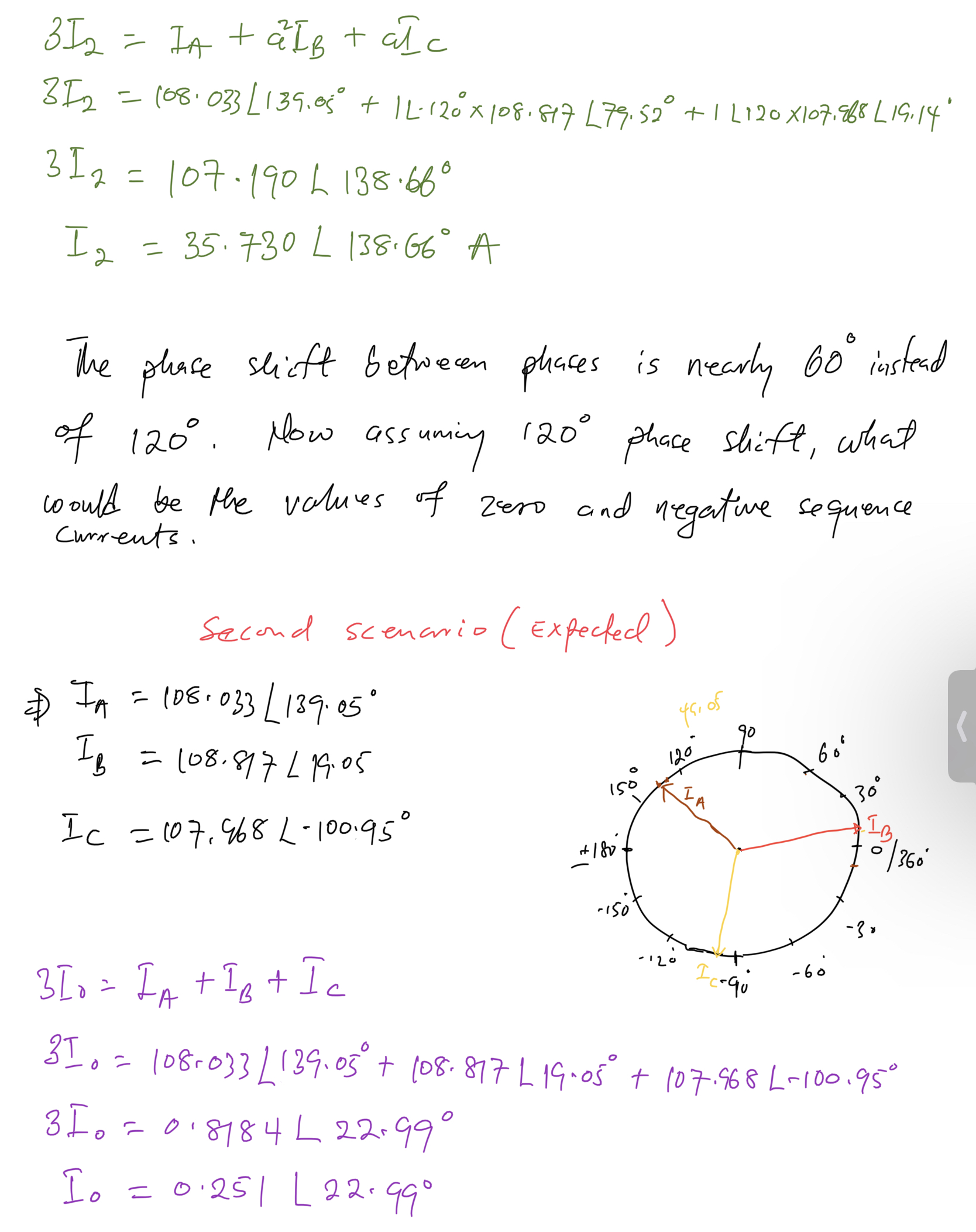
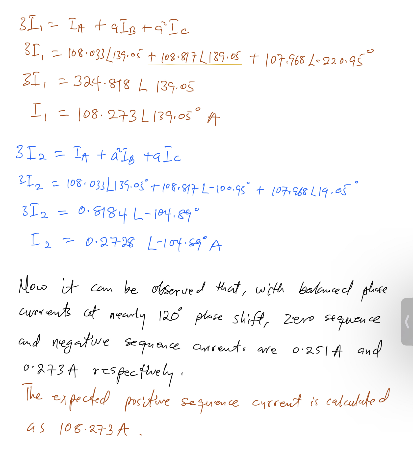
In figures 6 and 7, the calculated zero and negative sequence components are nearly zero.
Summary
In conclusion, this post analyzes three-phase systems to determine whether they are balanced or unbalanced.
Not every unbalance state indicates a faults but could be the results of loading where a phase maybe loaded more than other phases. However, you should check the level of such unbalance against what you have defined as a normal or abnormal condition for your facility or electrical system.
The goal of every electrical system is to run efficiently without problems but this is usually not the case in the real world of power systems. During commissioning of power projects, a lot may go on and important things go unchecked.
For an balanced three-phase system, the zero sequence and negative sequence components will be zero or nearly zero. One way to identify imbalances and potential issues in the electrical system is by using zero-sequence and negative-sequence components for analysis.
From such a determination, the protection system(s) (relay) will make a decision to trip or isolate the electrical system by comparing IG and IQ (if used) to pickup settings.
Having a good protection settings is not enough, but also making sure that the wiring of instrument transformers, system phase rotation (ABC or ACB) are done properly helps significantly.
Leave a comment or like if you find this post helpful.
Read more about symmetrical components with the download below.
References
- Marx, S., & Bender, D. (2013). An introduction to symmetrical components, system modeling and fault calculation. Washington State University Pullman, Washington.
- Amberg, A., & Rangel, A. (2014). Tutorial on symmetrical components. Selinc. Cachefly. Net, 1, 1-6.
Related
Discover more from ShaiLearning
Subscribe to get the latest posts sent to your email.

